


vSphere 7 with Kubernetes and NSXT 3.0
Table of Contents
Kuberenetes is a commodity. There I said it. Sure, I work in the Tanzu business unit of VMware, and we heavily value Kubernetes, as does VMware overall. VMware is a massive contributor to upstream Kubernetes–see Cluster API for example, and, well, there’s the whole Kubernetes-built-into-vsphere thing. But we are also very interested in what happens AFTER you have Kubernetes.
At VMware we make it easy to get Kubernetes dial tone so that you can get to the good stuff, the important stuff: deploying applications. Dial tone is the easy part, writing new apps quickly and getting them running in production…that’s hard. With that said, the majority of Tanzu’s focus is on what you do after you have Kubernetes, and of course getting apps in production.
But, let’s talk about the dial tone here, and especially NSXT 3.0.
Getting Kubernetes up and running in vSphere 7
There are many great blog posts on the matter:
- Tanzu vSphere 7 with Kubernetes on NSX-T 3.0 VDS Install Part 1: Overview
- Deploy a Tanzu Kubernetes cluster on vSphere 7
- Automated vSphere 7 and vSphere with Kubernetes Lab Deployment Script
- vSphere with Kubernetes
Any one of those will get you up and running. This post is my version of the above. That said, likely there is not quite enough here to get you completley up and running, but it will certainly provide you some direction.
- This is also a great post on troubleshooting
Networking
To enable “Workload Management” in vSphere 7 (aka Kubernetes) NSXT is required. Designing networks is not easy, and there are many paths that can be taken, but I’ll describe my overly simplified lab/PoC style path and you can diverge from it where ever you feel necessary.
I still have two nics in these ESXi hosts, I’ve left the various management interfaces, vmotion, storage, ect, on one nic and everything else, i.e. NSXT, on the other, though it’s not strictly necessary, and the advantages of NSXT would probably be better displayed with a single interface…but I’m too lazy to change it! Suffice it to say you can use a single nic now, which is great for PoC and lab work.
Virtual Switches
One of the biggest changes to networking with NSXT 3.0 and vSphere 7 is that VDS can be used by NSXT, instead of having to hand over a physical nic completely to NSX. This makes deployment a lot simpler!
With the release of vSphere 7 comes the vSphere Distributed Switch 7.0. This latest version comes with support for NSX-T Distributed Port Groups. Now, for the first time ever it is possible to use a single vSphere Distributed Switch for both NSX-T 3.0 and vSphere 7 networking! - Rutger Blom
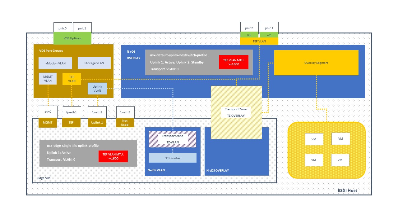
In a previous post I diagrammed a simple NSXT VDS and NVDS layout, shown below. This design has separate VDS and NVDS switches as well as a full nic provided to NSXT. (Right click and view image if you want to see it larger.)
For vSphere 7 and NSXT 3.0, it looks like the below. Note that in this setup we’ve got separate VLANs for the “Edge TEP” and the “Host TEP” but they have to be able to connect to one another at layer 3. So, now we need to have a MTU >=1600 on the VLANs, but also the router needs to be able to route packets >=1600 (but only between the Edge and Hosts TEP). Very important.
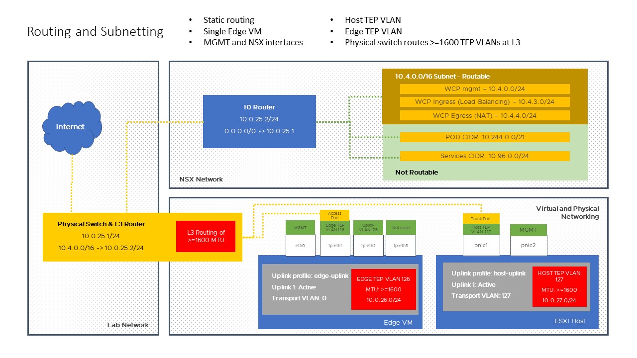
Wondering why we have two TEP networks? Here’s why:
You probably thinking why is there a need for a 2nd network specifically for Edge VMs. The reason is because we are using only 1 Physical NIC and therefore in order to “force” the Geneve TEP traffic egressing from the Edge VM to pass through the Physical NIC as the traffic would require routing when communicating with the ESXi hosts Geneve TEP interfaces. - Acepod blog
Here’s a list of NSX switches, er, well, “switch”.
[root@nested-esxi7-2:~] nsxdp-cli vswitch instance list
DvsPortset-1 (DNSX)              50 0e 6d 8d 5b b6 35 9c-b5 af c9 18 f5 76 b4 a9
Total Ports:4096 Available:4080
  Client                         PortID          DVPortID                             MAC                  Uplink
  Management                     100663301                                            00:00:00:00:00:00    n/a
  vmnic0                         2248146952      8                                    00:00:00:00:00:00
  Shadow of vmnic0               100663305                                            00:50:56:52:bd:fe    n/a
  vmk10                          100663307       739a47e2-3c93-483f-ac4d-df039cfd559d 00:50:56:6a:06:11    vmnic0
  vmk50                          100663308       40335d75-be5f-41f8-a5d5-5e4be4f9e996 00:50:56:66:71:7d    void
  vdr-vdrPort                    100663309       vdrPort                              02:50:56:56:44:52    vmnic0
  nsx-edge-1.eth2                100663310       19                                   00:50:56:8e:b5:2a    vmnic0
  nsx-edge-1.eth1                100663311       36                                   00:50:56:8e:9a:7d    vmnic0
  SupervisorControlPlaneVM       100663314       69576165-6ade-491f-a429-999655c87028 00:50:56:8e:b9:69    vmnic0
  (2).eth0
  SupervisorControlPlaneVM       100663315       f6fba7ac-e04b-4d7e-9f71-0aa07886c83f 04:50:56:00:c8:01    vmnic0
  (2).eth1
Note just the one VDS, which I’ve called “DNSX” in my deployment.
Subnetting and Layer 3 Routing
I am not the worlds greatest authority on networking. But one thing I think that I do that helps me to understand networking is separate broadcast domains from subnetting. A VLAN or a “segment” or a “logical switch”…these things are all about broadcast domains. What IPs are put onto those broadcast domains are completely separate items. Often people get quite confused and conflate the two.
A broadcast domain is a logical division of a computer network, in which all nodes can reach each other by broadcast at the data link layer. - CBTNuggets
So, as far as I’m concerned, in the NVDS/VDS layout diagram we’re really assigning network interfaces and applying broadcast domains to them. After we do that THEN we can decide what subnets will be assigned where, and, as well, think about layer 3 routing for t0, though that is relatively easy when using a simple static route to forward the networks handled by NSXT (in my lab, I give it a huge /16, haha).
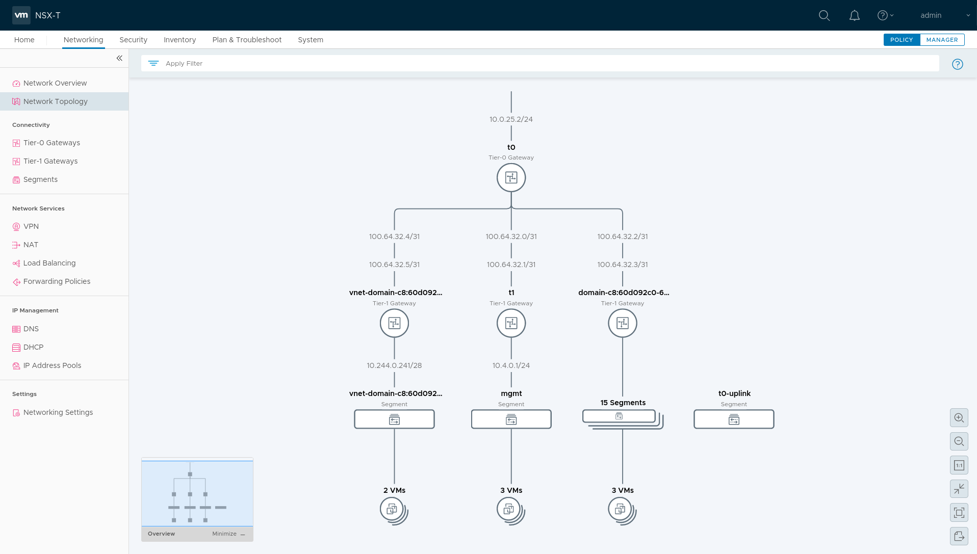
Here’s the nice topology visualization NSXT provides, and this topology occurs AFTER the Workload Control Plane (WCP) is deployed, as well as a Tanzu Kubernetes Grid cluster.
Here’s the subnets configured for WCP, which are entered initially during the “WCP Enable” wizard. The routable ingress and egress networks will be created by the enablement process, and, if using static routing, should be forwarded from the central network to the t0 router.
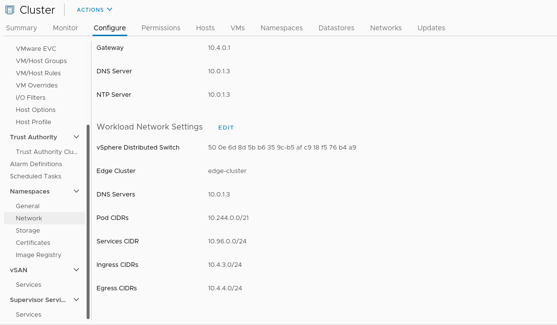
Not routable:
- Pod CIDRs = 10.244.0.0/21
- Services CIDR = 10.96.0.0/24
Routable:
- Ingress CIDRs (load balancing) = 10.4.3.0/24
- Egress CIDRs (NAT) = 10.4.4.0/24
NSXT Configuration
Ultimately, NSXT configuration is about setting up some profiles and applying them to edge VMs and ESXI hosts.
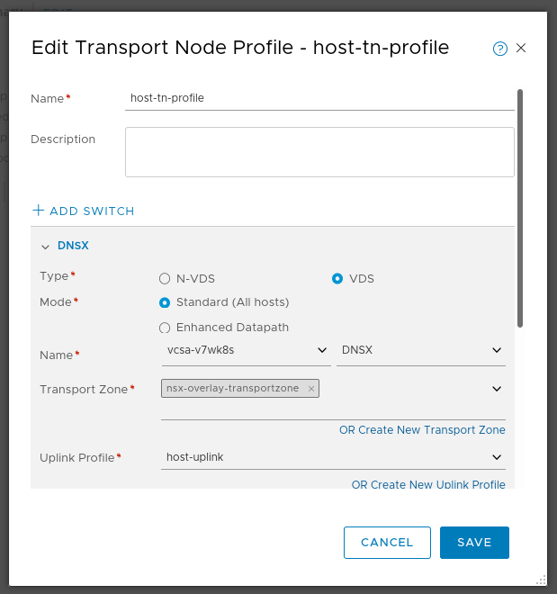
Host Transport Node Profile
Note how the switch in use is VDS, not NVDS.
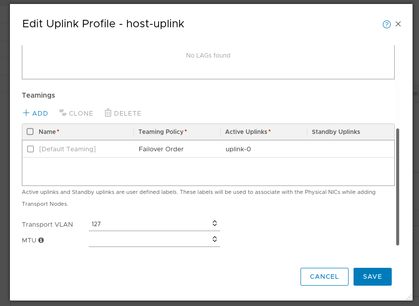
Uplink Profiles
Host uplink:
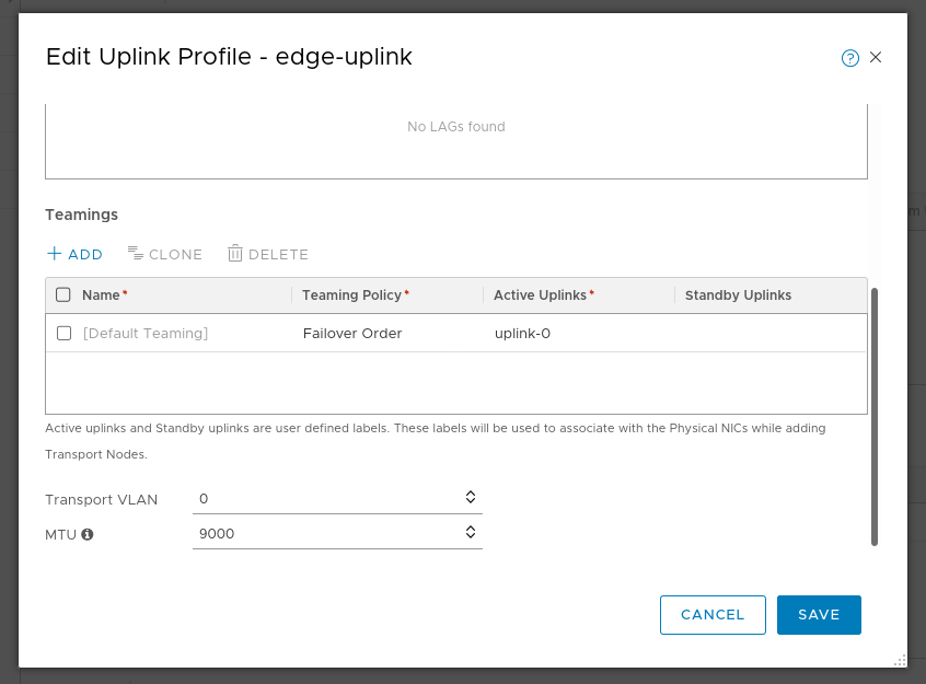
Edge uplink:
Conclusion
I’ve left out quite a bit about the actual clicking to install NSXT and vSphere 7 with Kubernetes. But at the end, what I’m most interested in is how the networking is laid out. The rest o the work to enable Kubernetes in vSphere 7 is quite straight forward, such as setting up the Kubernetes content library, creating a storage policy, etc. Once the network is up and running, it’s very, very easy to get WCP enabled and get access to the ability to deploy your own Tanzu Kubernetes Grid clusters.